 English
 русский
 Español
 Deutsch
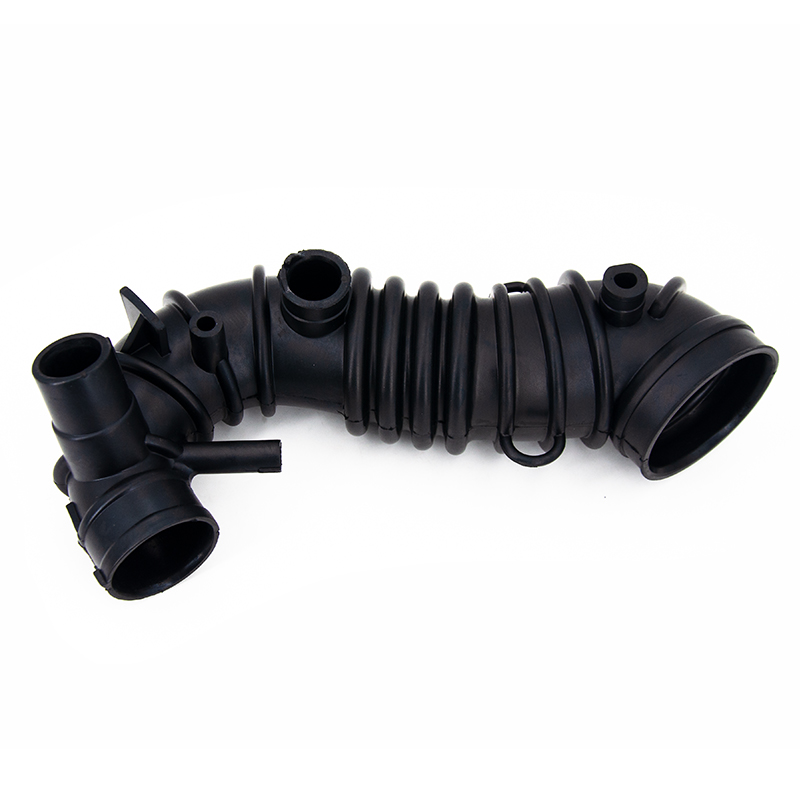
The air intake hose — also referred to as the intake duct, air induction hose, or air intake pipe — serves as the primary conduit through which ambient air is channelled from the air filter assembly into the throttle body and ultimately into the engine's combustion chambers. Its core function is to deliver a precise, controlled, and unobstructed flow of clean air to the engine at the correct velocity and volume to support efficient combustion. Beyond simply routing air, the intake hose plays critical roles in filtering and purifying incoming air, reducing intake noise, managing air temperature, preventing debris ingestion, and maintaining the air-to-fuel ratio that determines fuel efficiency, power output, and emissions. Because the engine's performance is directly dependent on the quality and quantity of air it receives, the design, material, and condition of the air intake hose have a measurable and direct impact on every dimension of engine operation.
Content
- 1 Primary Function: Directing Clean Air Into the Engine
- 2 Air Filtration and Purification: Protecting the Engine from Contamination
- 3 Air Temperature Management: Density, Power, and Efficiency
- 4 Noise Attenuation: Reducing Intake Induction Noise
- 5 Supporting the Mass Airflow Sensor: Enabling Precise Fuel Metering
- 6 Impact on Fuel Efficiency and Emissions
- 7 Material Selection: How Hose Construction Affects Performance and Durability
- 8 Role in Turbocharged and Supercharged Engines
- 9 Common Symptoms of a Failing or Damaged Air Intake Hose
- 10 Maintenance and Inspection: When to Replace the Air Intake Hose
Primary Function: Directing Clean Air Into the Engine
The most fundamental function of the air intake hose is to act as a sealed, low-restriction passage that guides ambient air from the atmosphere through the air filter and into the engine's induction system. This sounds straightforward, but the engineering demands placed on this component are substantial.
A modern petrol engine at full throttle consumes an enormous volume of air. A naturally aspirated 2.0-litre four-cylinder engine at 6,000 rpm draws in approximately 6,000 litres of air per minute — every litre of engine displacement processes roughly one litre of air per revolution. Any restriction, leak, or turbulence in the intake hose that reduces the volume or pressure of the incoming air charge immediately reduces power output, increases fuel consumption, and worsens emissions.
The intake hose achieves efficient air delivery through:
- Smooth internal bore geometry: The interior surface of a quality intake hose is as smooth as practical to minimise turbulent flow. Turbulence in the intake stream increases the energy required to accelerate air through the system, reducing the mass of air that reaches the cylinders at a given engine speed.
- Optimised diameter and cross-sectional area: The hose diameter is engineered to match the engine's air flow requirements. Too small a diameter creates a flow restriction that limits maximum power; too large a diameter reduces air velocity, which can impair the atomisation of fuel and the homogeneity of the air-fuel mixture at low engine speeds.
- Sealed connections: The hose must form airtight seals at both its connection to the air filter housing and its connection to the throttle body or mass airflow (MAF) sensor. Any air leak at these joints bypasses the air filter, admitting unfiltered air and — critically — air that has not been measured by the MAF sensor. Unmeasured air entering the system causes the engine management unit to miscalculate the fuel injection quantity, producing a lean misfire, rough idle, and increased emissions.
- Flexible routing capability: The engine moves dynamically on its mounts relative to the fixed airbox position. The intake hose must be flexible enough to accommodate this relative movement without cracking, collapsing, or developing leaks at connection points.
Air Filtration and Purification: Protecting the Engine from Contamination
Ambient air is far from clean — it contains dust particles, pollen, insects, water droplets, sand grains, and other particulate matter that would cause rapid and severe abrasive wear to engine components if allowed to enter the combustion chamber or the turbocharger (if fitted). The air intake hose works as an integral part of the filtration and air quality management system, channelling all incoming air through the air filter element before it reaches the engine.
The importance of this filtration role cannot be overstated. Dust particles with a diameter as small as 5–10 microns are capable of causing abrasive wear on cylinder bores, piston rings, and valve stems when present in sufficient concentrations. The air filter element in the housing connected to the intake hose is typically rated to capture particles down to 5–20 microns with high efficiency, protecting precision engine components that are manufactured to tolerances of a few microns.
The intake hose contributes to this filtration function in two ways:
- Sealed system integrity: By forming a fully sealed conduit, the intake hose ensures that all air passes through the filter element rather than bypassing it through cracks, loose connections, or holes in the hose body. Even a small crack in an intake hose large enough to admit a few litres of unfiltered air per minute can dramatically accelerate engine wear over thousands of operating hours.
- Prevention of water ingestion: The routing of the air intake hose is carefully designed to keep the intake opening away from areas where water pooling or spray can occur. Ingesting even a small quantity of liquid water into a running engine can cause catastrophic hydraulic lock — incompressible fluid in the cylinder prevents the piston from completing its compression stroke, bending the connecting rod or shattering the cylinder head. Quality intake hose designs include water deflectors and drainage provisions at the intake entry point.
Air Temperature Management: Density, Power, and Efficiency
The temperature of the air entering the engine has a direct and significant effect on power output and fuel efficiency. This is because colder air is denser than warm air — it contains more oxygen molecules per unit volume — and oxygen is the reactant that determines how much fuel can be burned in each combustion cycle.
The relationship between air temperature and density follows from the ideal gas law: at constant pressure, air density is inversely proportional to absolute temperature. A reduction in intake air temperature from 60°C to 20°C (a difference commonly achievable through routing optimisation) increases air density by approximately 11% — which, all else being equal, translates to a similar increase in maximum power output and a reduction in fuel consumption for a given power demand.
The air intake hose's routing determines where air is drawn from within the engine compartment. Two distinct strategies are used:
Cold Air Intake Routing
In cold air intake configurations, the intake hose routes air from a source away from the hot engine block — typically from the front of the vehicle or from a dedicated low-temperature air box positioned near the wheel arch. These designs draw cooler ambient air that has not been heated by radiator discharge, exhaust heat, or engine surface radiation. Cold air intake upgrades consistently show power increases of 5–15 horsepower on naturally aspirated engines by improving the density and oxygen content of the incoming charge.
Warm Air Intake (Intentional)
Some factory intake systems deliberately route a portion of their air from above the engine or from near the exhaust manifold during cold start conditions. Warmer air carries less tendency to cause combustion instability at very low temperatures and improves catalyst light-off speed. Modern electronic intake systems can blend warm and cold air sources using thermal actuators to optimise combustion stability and emissions throughout the operating temperature range.
Noise Attenuation: Reducing Intake Induction Noise
The rapid opening and closing of intake valves creates pressure pulsations in the intake tract that generate audible noise — the characteristic induction roar heard when an engine is revved with the air filter removed. In modern vehicles, managing this noise to remain within acceptable cabin comfort levels is a significant engineering consideration, and the air intake hose is one of the primary tools available for intake noise control.
Intake noise management is achieved through several hose design features:
- Resonator chambers: Specially shaped expansion chambers integrated into the intake hose or attached as side-branch resonators act as Helmholtz resonators — acoustic devices tuned to cancel specific frequency bands of intake noise. A resonator tuned to the dominant intake frequency of a four-cylinder engine at its most common operating speed can reduce in-cabin intake noise by 5–10 dB at the target frequency.
- Flexible damping material: The material of the intake hose itself plays a role in noise isolation. Rubber and thermoplastic elastomer (TPE) hoses absorb and damp vibrations that would be transmitted through a rigid metal or hard plastic intake system, reducing structurally radiated noise from the intake components.
- Expansion boxes and silencer sections: Some intake hose assemblies include deliberately enlarged cross-sectional sections that act as acoustic silencers — the sudden expansion reduces the velocity of pressure pulsations and attenuates their amplitude before they propagate to the atmosphere or into the cabin through the firewall.
Conversely, performance-oriented vehicles and aftermarket tuners sometimes deliberately design intake hoses with minimal resonator attenuation to allow the induction sound to be heard in the cabin — treating the characteristic induction noise as a desirable driving engagement element rather than a nuisance to be suppressed.
Supporting the Mass Airflow Sensor: Enabling Precise Fuel Metering
In virtually all modern fuel-injected engines, the air intake hose contains or directly connects to the mass airflow (MAF) sensor — a critical electronic component that measures the precise mass of air entering the engine in real time. The engine control unit (ECU) uses the MAF sensor signal as the primary input for calculating the correct fuel injection quantity at every operating point.
For the MAF sensor to function accurately, the air flowing past its sensing element must be:
- Laminar (non-turbulent): Turbulent airflow past the MAF sensor creates fluctuating signals that the sensor cannot accurately interpret, leading to erratic fuel metering. The intake hose typically includes a straight run of 10–15 cm before and after the MAF sensor to allow turbulence to decay and establish laminar flow at the measurement point.
- Uncontaminated by oil mist: Many engines route crankcase ventilation gases containing oil mist back into the intake system upstream of the throttle body. If this oil mist deposits on the MAF sensor's hot wire or film element, it insulates the sensing surface and causes a systematic error in the air mass reading — typically causing a rich fuel trim as the sensor under-reads actual air flow. The intake hose routing must manage this contamination risk to protect MAF sensor accuracy.
- Sealed from unmetered air: As noted above, any air that enters the intake system downstream of the MAF sensor — through cracks, loose clamps, or deteriorated seals — is not measured and causes the ECU to inject less fuel than the actual air charge requires, producing a lean condition that causes misfires, rough running, and increased NOx emissions.
Impact on Fuel Efficiency and Emissions
The air intake hose's condition and design quality have a direct, quantifiable impact on the fuel economy and emissions performance of the vehicle. These connections are well-established in automotive engineering and explain why the intake hose is treated as a critical maintenance and performance component rather than a passive rubber conduit.
Effect of Intake Restriction on Fuel Economy
A partially blocked or collapsed intake hose reduces the volume of air available to the engine at any given throttle position. The engine compensates by opening the throttle further than normal to maintain power output — this increases pumping losses across the throttle plate, directly increasing fuel consumption. A restriction that reduces peak air flow by 10% typically increases fuel consumption by a comparable margin under load conditions, since the engine must work harder to produce the same output.
Effect of Air Leaks on Emissions
An intake hose air leak downstream of the MAF sensor creates a persistent lean fuel condition. Lean combustion at normal operating temperatures produces elevated levels of nitrogen oxides (NOx) — a regulated pollutant — because the excess oxygen in the combustion chamber drives higher peak combustion temperatures. Simultaneously, the lean condition causes incomplete combustion at idle and low-load conditions, increasing hydrocarbon (HC) emissions. A simple cracked or loose intake hose can therefore cause a vehicle to fail its emissions inspection while simultaneously increasing fuel consumption and reducing power.
Contribution to Stoichiometric Air-Fuel Ratio Maintenance
The stoichiometric air-fuel ratio for petrol combustion is 14.7:1 by mass — the precise proportion of air to fuel that achieves complete combustion with no excess oxygen and no unburned fuel. The three-way catalytic converter, which reduces NOx, CO, and HC emissions simultaneously, operates effectively only when the air-fuel ratio is held within a narrow window of approximately ±0.5% of stoichiometry. An intake hose leak that introduces unmetered air shifts the actual ratio lean of this window, degrading catalytic converter efficiency and causing real-world emissions to exceed regulatory limits even when the engine is otherwise functioning correctly.
Material Selection: How Hose Construction Affects Performance and Durability
The material from which an air intake hose is manufactured determines its ability to withstand the engine bay environment — which exposes components to heat, ozone, engine oils, fuel vapour, coolant, vibration, and UV radiation — while maintaining its dimensional integrity and airtight seal over the vehicle's service life.
| Material | Temperature Resistance | Ozone / Chemical Resistance | Flexibility | Typical Application |
|---|---|---|---|---|
| EPDM Rubber | -40°C to +150°C | Excellent | High | Standard OEM intake hoses, flexible sections |
| Silicone Rubber | -60°C to +200°C | Excellent | High | Performance, turbo applications, high-temp zones |
| Thermoplastic Elastomer (TPE) | -40°C to +130°C | Good | Moderate | Modern OEM hoses, cost-effective alternatives |
| Reinforced Nylon / PA | -40°C to +140°C | Very Good | Low (semi-rigid) | Rigid intake sections, duct tubing near filter housing |
| Aluminised Steel | Up to +400°C | Good | None (rigid) | Turbocharger inlet and outlet pipes, intercooler pipes |
EPDM rubber is the most widely used material for standard production vehicle intake hoses due to its excellent balance of temperature resistance, ozone and UV resistance, chemical compatibility with engine bay fluids, and cost effectiveness. Silicone hoses offer superior high-temperature performance and are favoured in turbocharged and high-performance applications, though at higher cost. Reinforced fabric or wire braiding is added to hoses in locations where collapse under vacuum is a risk — the intake system operates under significant vacuum at part throttle, and an unbonded straight-walled hose section could collapse inward, causing a severe and intermittent intake restriction.
Role in Turbocharged and Supercharged Engines
In engines fitted with turbochargers or superchargers, the air intake hose system becomes significantly more complex and the demands on hose material and construction increase substantially. The intake system in a turbocharged engine is divided into two distinct pressure zones that require different hose specifications:
Cold Side (Pre-Turbocharger)
The cold side intake hose connects the air filter to the compressor inlet of the turbocharger. This section operates at or slightly below atmospheric pressure and at relatively low temperatures (ambient to approximately 60°C). Hose requirements here are similar to naturally aspirated applications, with the addition of needing to sustain the slight vacuum created by the compressor inlet without collapsing.
Hot Side (Post-Turbocharger, Pre-Intercooler)
Air exiting the turbocharger compressor is pressurised and has been heated by the compression process to temperatures of 100°C to 200°C or higher in high-boost applications. The hose connecting the turbocharger outlet to the intercooler inlet must sustain these elevated temperatures while also containing positive pressures of 0.5 to 3.0 bar above atmospheric on a sustained basis. Silicone hoses or aluminised steel pipes with silicone couplers are the standard specification for this application.
Charge Air Cooler to Throttle Body (Cold Side, Post-Intercooler)
After the intercooler reduces the compressed air temperature (typically to within 30–50°C of ambient), the cooled, pressurised air is routed through another hose section to the throttle body. This section still carries pressurised air but at lower temperature. The total pressure acting on the hose at this point can be 1.5 to 4.0 bar absolute in high-performance applications, requiring hoses with adequate burst pressure ratings and secure clamping at all connections.
A boost pipe failure in a turbocharged system — a split hose or a blown coupling — causes an immediate and total loss of boost pressure, reducing the engine to naturally aspirated performance or worse, and in some cases causing the engine to enter limp-home mode if boost pressure sensors detect the anomaly. This illustrates why intake hose integrity is even more critical in turbocharged applications than in naturally aspirated engines.
Common Symptoms of a Failing or Damaged Air Intake Hose
Because the air intake hose is a critical element of the engine's air management system, its deterioration produces recognisable symptoms that alert the driver or technician to a developing problem before it causes secondary engine damage. Recognising these symptoms early allows for relatively inexpensive hose replacement rather than the much more costly repairs that can result from continued operation with a compromised intake system.
- Rough idle and engine misfires: An air leak downstream of the MAF sensor introduces unmetered air that leans out the fuel mixture, causing unstable combustion at idle when fuel demand is low and the effect of unmetered air is proportionally largest.
- Check engine light (CEL) illumination: The ECU detects the lean fuel trim caused by an intake leak and typically sets diagnostic trouble codes related to fuel system leanness (P0171 — System Too Lean, Bank 1 being the most common) or MAF sensor performance codes if the leak is large enough to cause obvious measurement discrepancy.
- Reduced power and poor throttle response: A collapsing or severely cracked intake hose reduces the air flow available to the engine, particularly at higher loads and engine speeds. The driver experiences this as sluggish acceleration, a flat spot when opening the throttle, or a reduction in top-end power.
- Increased fuel consumption: Both intake restrictions (which increase pumping losses) and air leaks (which cause lean-running conditions that the fuel trim system attempts to correct by adding fuel) result in increased fuel consumption that may be apparent on a trip computer over time.
- Loud induction noise: A crack or split in the intake hose allows high-velocity intake air pulses to escape into the engine bay, producing a loud hissing or whooshing sound that is most audible during acceleration. This noise is frequently the first symptom that draws the driver's attention to an intake hose problem.
- Black smoke from the exhaust (turbocharged engines): In a turbocharged engine, a boost pipe failure causes the engine management system to continue fuelling for the expected boost pressure that is no longer present, resulting in a rich over-fuelled condition that produces black exhaust smoke until the ECU detects and adjusts for the anomaly.
Maintenance and Inspection: When to Replace the Air Intake Hose
Unlike consumable components such as oil filters or spark plugs, the air intake hose does not have a fixed replacement interval in most vehicle service schedules. It is designed to last the life of the vehicle under normal conditions. However, engine bay heat, ozone, vibration, and UV exposure progressively degrade rubber-based hoses, and inspection at regular service intervals — or whenever related symptoms are reported — is good practice.
- Visual inspection for cracking and hardening: Rubber intake hoses that have become hard, brittle, or visibly cracked are at high risk of failure under heat cycles and should be replaced proactively. Squeezing the hose by hand should produce a supple, flexible feel — a hard, unyielding hose indicates advanced degradation.
- Check all clamps and connections: Inspect hose clamps at both ends of the intake hose for tightness and corrosion. Loose clamps are a common cause of air leaks that develop gradually as vibration works the connection loose. Corroded clamps should be replaced rather than simply re-tightened.
- Inspect for collapse or deformation: Look along the length of the hose for any sections that appear collapsed, kinked, or permanently deformed. These sections restrict air flow and may indicate that the hose's internal spiral wire or fabric reinforcement has failed.
- Smoke test for air leaks: A workshop-grade smoke test introduces pressurised smoke into the intake system with the engine off, allowing any leaks to be identified by smoke emergence. This is the most definitive method for locating sm


